After a series of previous articles laying the groundwork, the files for PS2 savegame 3D icons have all been parsed. In this article, we will begin to explore how to render the 3D icons using the following tools, aiming to achieve a rendering as close as possible to the original effect on the PS2 console.
- Python3
- PyGame
- Numpy
- ModernGL
- PyGLM
01 Initialize PyGame and ModernGL#
The first step is to initialize PyGame, setting the window size to 640x480 and the FPS to 60. We enable OpenGL rendering mode and set the OpenGL version to 3.3.
1
2
3
4
5
6
7
8
9
| import pygame as pg
pg.init()
pg.display.gl_set_attribute(pg.GL_CONTEXT_MAJOR_VERSION, 3)
pg.display.gl_set_attribute(pg.GL_CONTEXT_MINOR_VERSION, 3)
pg.display.gl_set_attribute(pg.GL_CONTEXT_PROFILE_MASK, pg.GL_CONTEXT_PROFILE_CORE)
pg.display.set_mode((640, 480), flags=pg.OPENGL | pg.DOUBLEBUF)
self.clock = pg.time.Clock()
self.clock.tick(60)
|
Next, initialize ModernGL. This is very simple; just create a context and enable depth testing and face culling.
1
2
3
4
| import moderngl as mgl
self.ctx = mgl.create_context()
self.ctx.enable(flags=mgl.DEPTH_TEST | mgl.CULL_FACE)
|
02 Obtain Vertex, Texture, Normal Data, etc.#
This part of the content was detailed in the previous article Parsing PS2 Game Save 3D Icon, so I won’t go into detail here. Below is just the data structure of icon.sys for reference.
 1
 2
 3
 4
 5
 6
 7
 8
 9
10
11
12
13
14
15
16
17
18
19
20
21
22
23
| struct IconSys {
char magic[4];
uint16 unknown; // ignore
uint16 subtitle_line_break;
uint16 unknown; // ignore
uint32 bg_transparency;
uint32 bg_color_upper_left[4];
uint32 bg_color_upper_right[4];
uint32 bg_color_lower_left[4];
uint32 bg_color_lower_right[4];
float32 light_pos1[4];
float32 light_pos2[4];
float32 light_pos3[4];
float32 light_color1[4];
float32 light_color2[4];
float32 light_color3[4];
float32 ambient[4];
char subtitle[68];
char icon_file_normal[64];
char icon_file_copy[64];
char icon_file_delete[64];
char zeros[512]; // ignore
};
|
03 Coordinate System#
Here, we create a coordinate system using the right-hand system, but the original vertices are inverted along the y-axis, as shown in Figure A. Therefore, our subsequent work will be conducted in the transformed coordinate system shown in Figure B.
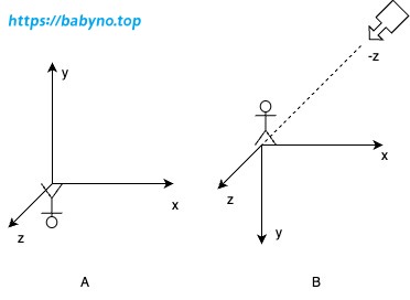
View Matrix#
In Figure B, the camera position extends in the negative direction of the z-axis. We move the camera slightly downward along the negative y-axis to adjust the viewpoint slightly above the icon, rather than focusing on its feet. Thus, we set the camera position coordinates to (0, -2, -10). As we need to invert the y-axis, we can directly set the camera’s upward direction to the negative direction of the y-axis. This creates the lookAt matrix as follows:
1
2
3
| self.position = glm.vec3(0, -2, -10)
self.up = glm.vec3(0, -1, 0)
self.view = glm.lookAt(self.position, glm.vec3(0, -2, 0), self.up)
|
Projection Matrix#
The projection matrix can be obtained using the following formula:
1
| self.proj = glm.perspective(glm.radians(50), window_width / window_height, 0.1, 100)
|
Model Matrix#
The purpose of creating the model matrix is to control the positional changes of the model object in 3D space. Here, the model object needs to rotate 360 degrees around the y-axis.
1
2
3
4
5
6
| # Initialize the model matrix
self.m_model = glm.mat4()
# Rotate the model around the y-axis by an angle corresponding to the elapsed time.
# The initial 180 degrees is to make the model initially face away from the screen, closer to the behavior of the PS2 console.
m_model = glm.rotate(self.m_model, glm.radians(180) + animation_time / 2,
glm.vec3(0, 1, 0))
|
05 Create Shaders#
Here, we need to create four shaders in total:
- Background Vertex Shader
- Background Fragment Shader
- Icon Vertex Shader
- Icon Fragment Shader
Background Shader#
The background shader is relatively simple. We just need to create a rectangle that covers the entire coordinate system and place it on the coordinate plane farthest from the camera. Referring to the diagram above (Figure B), this plane should be at z-axis 0.9999. The coordinates of the four vertices of this rectangle are (-1, 1), (-1, -1), (1, -1), and (1, 1), respectively. The corresponding colors can be parsed from icon.sys. With these four vertices and colors, we can construct the background VBO and VAO. Further details are not provided here.
 1
 2
 3
 4
 5
 6
 7
 8
 9
10
11
12
| // bg.vert
#version 330 core
in vec2 vertexPos;
in vec4 vertexColor;
out vec3 fragColor0;
void main() {
fragColor0 = vertexColor.rgb;
gl_Position = vec4(vertexPos.xy, 0.9999, 1.0);
}
|
 1
 2
 3
 4
 5
 6
 7
 8
 9
10
11
12
| // bg.frag
#version 330 core
in vec3 fragColor0;
out vec4 fragColor;
uniform float alpha0;
void main() {
fragColor = vec4(fragColor0, alpha0);
}
|
Icon Shader#
The Icon shader will be relatively complex. Let’s start by attempting to render the Icon vertices. Do you remember that each icon has multiple shapes? Shapes are related to animation. For now, we will only select one shape to compose the VBO and VAO.
 1
 2
 3
 4
 5
 6
 7
 8
 9
10
11
12
| // icon.vert
#version 330 core
in vec4 vertexPos;
uniform mat4 proj;
uniform mat4 view;
uniform mat4 model;
void main() {
gl_Position = proj * view * model * vec4(vertexPos.xyz, 1);
}
|
1
2
3
4
5
6
7
8
| // icon.frag
#version 330 core
out vec4 fragColor;
void main() {
fragColor = vec4(0, 0, 0, 1);
}
|
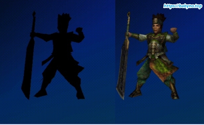
Below is the result after running the code:
Adding Textures#
Building upon the previous setup, introduce texture coordinates and texture data.
 1
 2
 3
 4
 5
 6
 7
 8
 9
10
11
12
13
14
15
16
17
18
19
| // icon.vert
#version 330 core
in vec4 vertexPos;
in vec2 texCoord;
in vec4 vertexColor;
out vec4 fragColor0;
out vec2 uv0;
uniform mat4 proj;
uniform mat4 view;
uniform mat4 model;
void main() {
uv0 = texCoord;
fragColor0 = vertexColor;
gl_Position = proj * view * model * vec4(vertexPos.xyz, 1);
}
|
 1
 2
 3
 4
 5
 6
 7
 8
 9
10
11
12
13
14
15
| // icon.frag
#version 330 core
in vec2 uv0;
in vec4 fragColor0;
out vec4 fragColor;
uniform sampler2D texture0;
void main() {
float alpha = fragColor0.a;
vec3 color = fragColor0.rgb * texture(texture0, uv0).rgb;
fragColor = vec4(color, alpha);
}
|
Adding Lighting#
Building upon the previous setup, introduce light sources, ambient light, and normal data.
 1
 2
 3
 4
 5
 6
 7
 8
 9
10
11
12
13
14
15
16
17
18
19
20
21
22
23
24
| // icon.vert
#version 330 core
in vec4 vertexPos;
in vec2 texCoord;
in vec4 vertexColor;
in vec4 normal;
out vec4 fragColor0;
out vec2 uv0;
out vec3 normal0;
out vec3 fragPos0;
uniform mat4 proj;
uniform mat4 view;
uniform mat4 model;
void main() {
uv0 = texCoord;
fragColor0 = vertexColor;
normal0 = mat3(model) * normalize(normal.xyz);
gl_Position = proj * view * model * vec4(vertexPos.xyz, 1);
fragPos0 = gl_Position.xyz;
}
|
 1
 2
 3
 4
 5
 6
 7
 8
 9
10
11
12
13
14
15
16
17
18
19
20
21
22
23
24
25
26
27
28
29
30
31
32
33
34
| // icon.frag
#version 330 core
#define MAX_NUM_TOTAL_LIGHTS 3
in vec2 uv0;
in vec4 fragColor0;
in vec3 normal0;
in vec3 fragPos0;
out vec4 fragColor;
struct Light {
vec4 pos;
vec4 color;
};
uniform sampler2D texture0;
uniform vec4 ambient;
uniform Light lights[MAX_NUM_TOTAL_LIGHTS];
void main() {
vec3 normal = normalize(normal0);
float alpha = fragColor0.a;
vec3 color = fragColor0.rgb * texture(texture0, uv0).rgb;
vec3 diffuse = vec3(0.0, 0.0, 0.0);
for (int i = 0; i < MAX_NUM_TOTAL_LIGHTS; i++) {
vec3 lightDir = normalize(lights[i].pos.xyz - fragPos0);
float diff = max(dot(lightDir, normal), 0.0);
diffuse += diff * lights[i].color.rgb;
}
color = (ambient.rgb + diffuse) * color;
fragColor = vec4(color, alpha);
}
|
Animation Effects#
Animation effects involve rendering vertex data of different shapes by shaders over time. We can design a timer and a counter to determine which shape’s vertices should be rendered at the current time.
frame_length: The actual number of frames required to complete the animation effect, with a frame rate of 60FPS.animation_time: The elapsed time of the animation.anim_speed: The playback speed of the animation.frame_length / animation_shapes: Number of frames contained in one shape.
1
2
3
4
| animation_time = time.time() - self.start_time
curr_frame = int(animation_time * self.window.fps * self.icon.anim_speed)
% self.icon.frame_length
curr_shape = int(curr_frame // (self.icon.frame_length / self.icon.animation_shapes))
|
Achieving Smooth Animation Transitions#
To achieve smooth animation transitions, we need to use vertex interpolation techniques in the shader. When sending vertex data to the shader, we send the vertex data of both the current shape and the next shape simultaneously. Then, based on the time factor, the shader will automatically calculate the vertices between the two shapes.
tween_factor: Calculates the percentage of frames occupied by the current timestamp within the entire shape.
1
2
| curr_frame_in_shape = curr_frame % frames_in_shape / frames_in_shape
tween_factor = glm.float32(curr_frame_in_shape)
|
 1
 2
 3
 4
 5
 6
 7
 8
 9
10
11
12
13
14
15
16
17
18
19
20
21
22
23
24
25
26
27
| // icon.vert
#version 330 core
in vec4 vertexPos;
in vec2 texCoord;
in vec4 vertexColor;
in vec4 nextVertexPos;
in vec4 normal;
out vec4 fragColor0;
out vec2 uv0;
out vec3 normal0;
out vec3 fragPos0;
uniform mat4 proj;
uniform mat4 view;
uniform mat4 model;
uniform float tweenFactor;
void main() {
uv0 = texCoord;
fragColor0 = vertexColor;
normal0 = mat3(model) * normalize(normal.xyz);
vec4 basePos = vec4(mix(vertexPos.xyz, nextVertexPos.xyz, tweenFactor), 1.0);
gl_Position = proj * view * model * basePos;
fragPos0 = gl_Position.xyz;
}
|
 1
 2
 3
 4
 5
 6
 7
 8
 9
10
11
12
13
14
15
16
17
18
19
20
21
22
23
24
25
26
27
28
29
30
31
32
33
34
| // icon.frag
#version 330 core
#define MAX_NUM_TOTAL_LIGHTS 3
in vec2 uv0;
in vec4 fragColor0;
in vec3 normal0;
in vec3 fragPos0;
out vec4 fragColor;
struct Light {
vec4 pos;
vec4 color;
};
uniform sampler2D texture0;
uniform vec4 ambient;
uniform Light lights[MAX_NUM_TOTAL_LIGHTS];
void main() {
vec3 normal = normalize(normal0);
float alpha = fragColor0.a;
vec3 color = fragColor0.rgb * texture(texture0, uv0).rgb;
vec3 diffuse = vec3(0.0, 0.0, 0.0);
for (int i = 0; i < MAX_NUM_TOTAL_LIGHTS; i++) {
vec3 lightDir = normalize(lights[i].pos.xyz - fragPos0);
float diff = max(dot(lightDir, normal), 0.0);
diffuse += diff * lights[i].color.rgb;
}
color = (ambient.rgb + diffuse) * color;
fragColor = vec4(color, alpha);
}
|
The final result:
06 Closing Words#
All the code can be downloaded from here. As I mentioned in my first article, the original intention of this series was to commemorate the passing of youth and the everlasting passion for technology. With this conclusion, it’s like fulfilling a dream from my youth.
07 References#