01 Preface
As an 80s gamer, the PS2 game console has always held a special place in my heart. Over 20 years have passed, yet recently, due to the emulator, I rediscovered it. After revisiting games for a while, I had a sudden idea: could I recall my younger self with my current knowledge? So, I began creating this series of articles, starting with analyzing the file system of the PS2 memory card and gradually delving into its file storage mechanism and the save files of each game. My goal is to ultimately simulate the classic 3D character rotation effect from game saves using Python and OpenGL, commemorating the classic game console that once accompanied me through my youth.
This is the first piece in the series, analyzing the file system of the PS2 memory card.
02 Glossary
Memory CardsThe PS2 memory cards used for the PlayStation 2 console are specialized media that can be inserted into the host system. These two devices operate independently of each other.NAND FlashThe internal chip used by the PS2 memory card, a type of non-volatile storage device.Save FilesThe storage card image files used by the PS2 emulator, saved on the computer disk where the emulator is located, with the.ps2extension, are the target of our analysis in this article.SuperBlockThe first page on the memory card where important information about the structure of the file system is kept.pageThe basic addressable unit on a memory card. Corresponds to page on the flash device used in the memory card, and is analogous to a sector on hard disk.clusterThe unit of allocation used in the file system. A cluster is one or more pages in size.blockThe minimum erasure unit of the file system, the size of the block, is defined in the superblock.Erasure: When flash memory is initialized, each bit in a page is set to 1. Writing operations can set a bit to 0, but cannot restore it to 1. Erasure is the only way to restore a bit to 1, but the disadvantage is that erasure is done in blocks. Even if only one bit of data is modified, an entire block must be erased first, and then each page of the block is restored using writing operations. This is also a common reason for the relatively slow speed of PS2 game saves.FAT: File Allocation Table, similar to the file allocation table in FAT16 and FAT32 file systems. Since files can be saved on multiple clusters, and clusters can be non-contiguous, to ensure that all contiguous or non-contiguous cluster addresses can be retrieved when accessing files, the file allocation table uses a “cluster chain” record method, which is a linked list.ifc: Indirect FAT Cluster, which is a cluster that contains a list of FAT clusters on the memory card.ifc_list: An array ofifc, defined in the superblock. Through it,ifcclusters can be found.ECC: Error Correction Code, a flash memory feature. When writing to a page, error correction code calculation needs to be performed on each page and written to the spare area.spare area: A space reserved in each page to store ECC.entry: A basic information unit that stores files or directories on the memory card, such as file (directory) name, size, and the number of the first cluster.
03 File System Structure
Note: Here, a standard 8MB memory card is used as an example.
3.1 Data Structures
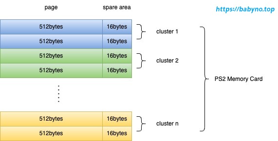
From the superblock, we can determine that the size of a page is 512 bytes, and the size of a cluster is 2 pages. The size of the spare area can be obtained from the formula (page_len / 128) * 4, which is 16 bytes. Therefore, the basic data structure of the file system is as shown in the figure:
3.2 Logical Structure
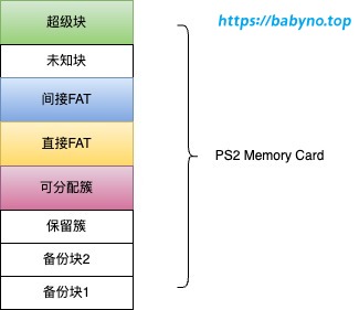
Having understood the most basic data structures, let’s now divide the logical structure of the memory card. As shown in the figure below, a memory card can be roughly divided into several logical blocks. (The black and white parts are not relevant to this article and can be ignored.) Note: The minimum unit composing logical blocks is a cluster.
Superblock
Located at the beginning of the entire file system (the first cluster), the first 340 bytes. This is the only part of the file system with a fixed position. The figure below illustrates a superblock of a memory card file.
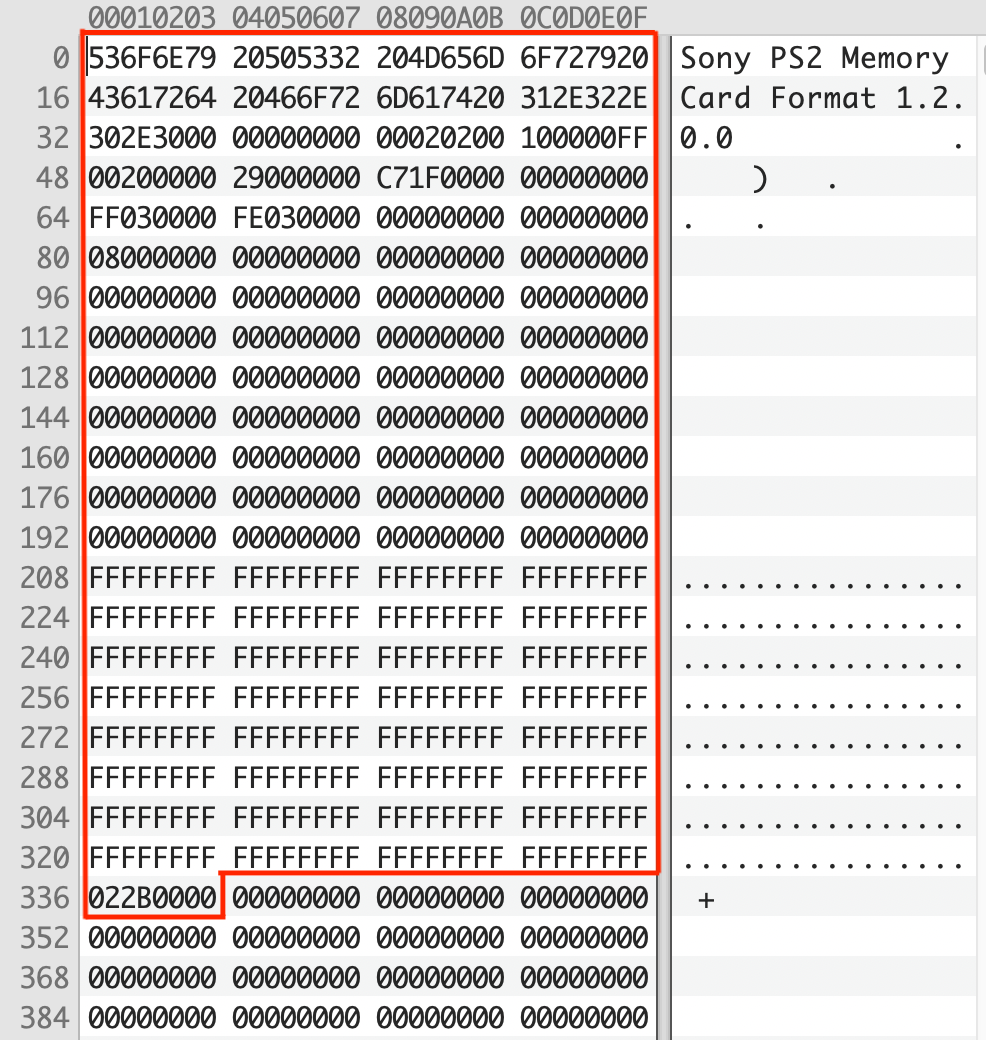
Note: The byte order of PS2 memory card is little-endian.
| Offset | Name | Length | Default | Description |
|---|---|---|---|---|
| 0 | magic | byte[28] | - | Fixed string “Sony PS2 Memory Card Format”, indicating successful initialization of the card |
| 28 | version | byte[12] | 1.X.0.0 | Version number |
| 40 | page_len | uint16 | 512 | Size of a page in bytes |
| 42 | pages_per_cluster | uint16 | 2 | Number of pages in a cluster |
| 44 | pages_per_block | uint16 | 16 | Number of pages in a block |
| 46 | - | uint16 | 0xFF00 | Unknown |
| 48 | clusters_per_card | uint32 | 8192 | Total size of the card in clusters |
| 52 | alloc_offset | uint32 | 41 | First allocatable cluster |
| 56 | alloc_end | uint32 | 8135 | Last allocatable cluster |
| 60 | rootdir_cluster | uint32 | 0 | First cluster of the root directory, relative to alloc_offset |
| 64 | backup_block1 | uint32 | 1023 | Not used in this article |
| 68 | backup_block2 | uint32 | 1022 | Not used in this article |
| 80 | ifc_list | uint32[32] | 8 | Indirect FAT cluster list, only one indirect FAT cluster on a standard 8MB card |
| 208 | bad_block_list | uint32[32] | -1 | Not used in this article |
| 336 | card_type | byte | 2 | Must be 2, indicating a PS2 memory card |
| 337 | card_flags | byte | 0x52 | Physical characteristics of the memory card |
The fields page_len, pages_per_cluster, pages_per_block, and clusters_per_card define the basic geometric structure of the file system. The ifc_list can be used to access the FAT, and rootdir_cluster gives the first cluster of the root directory. Both the FAT and cluster offsets in directory entries are related to alloc_offset.
FAT
The file allocation table is a linked list. When you find the starting cluster of a file, imagine there are two threads: thread X reads the content (i.e., data) of this cluster, while thread Y searches the FAT for the next cluster to be read by thread X, and this process continues in a loop. Of course, two threads are not necessary. Here’s a diagram illustrating this working mechanism:
- Given a file A with the starting cluster being 8.
- Thread X reads the first block of data A0 from cluster 8.
- Thread Y searches the FAT and finds that the next cluster after 8 is 13.
- Thread X continues to read data A1 from cluster 13.
- Thread Y searches the FAT again and finds that the next cluster after 13 is 7.
- This process continues indefinitely.
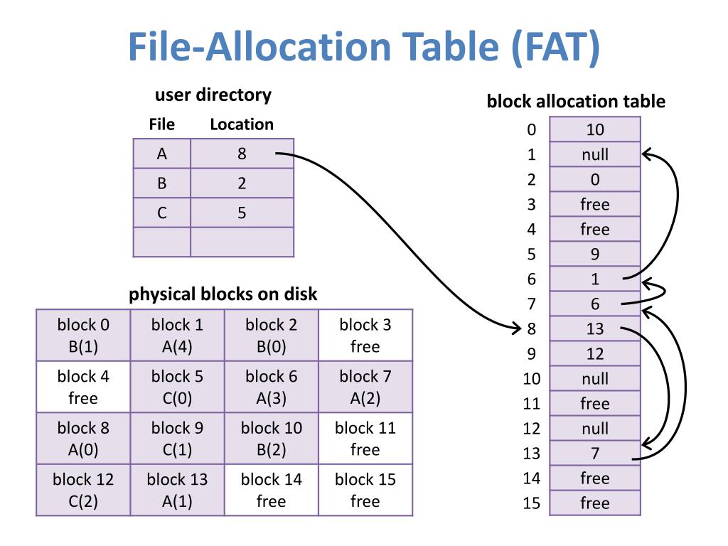
Source:https://www.slideserve.com/yahto/file-system-implementation
Direct FAT
As mentioned earlier, both direct FAT and indirect FAT are stored in clusters. The data within clusters must have a well-defined structure to allow us to easily parse it into FAT chains. The structure of FAT within a cluster can be imagined as follows:
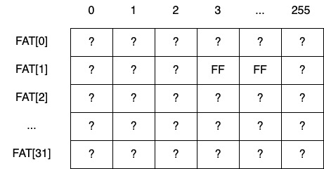
This is a matrix M, where rows represent the clusters where FAT resides, and columns represent the data within each FAT cluster. Each FAT cluster contains an array of 4-byte 32-bit integers, with a total of 1024 / 4 = 256 elements, resulting in 256 columns in the matrix. How many clusters are there in total for FAT? This can be parsed from the clusters of the indirect FAT, which we’ll discuss later. Here, FAT occupies a total of 32 clusters, so the matrix has 32 rows.
The size of matrix M is 32 * 256 = 8192, meaning this FAT can manage 8192 clusters. Suppose we want to find the position row and column of cluster n in the matrix, this can be calculated simply as:
| |
Now that the position has been calculated, we can obtain the corresponding value. Yes, this value ? represents the next cluster. By continuously looping until the retrieved value is 0xFFFFFFFF, it indicates the end of the cluster chain, and no further search is needed.
Note: The values stored in the FAT table are 32-bit, with the highest bit as 8 representing a normal used cluster, and other values indicating unallocated clusters. When the highest bit is 8, the lower 31 bits are taken as the integer value. The value 0xFFFFFFFF represents the end of the cluster chain.
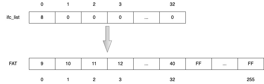
Indirect FAT
An earlier question was left unanswered: why does FAT occupy 32 clusters?
In the superblock, there’s a field called ifc_list, which is a 4-byte 32-bit integer array. Imagine the matrix mentioned earlier. ifc_list is a matrix with only one row, although it has 32 elements, only the first one has a value, which is 8 representing the indirect FAT cluster ifc. Parse the contents of cluster 8 as described earlier, forming another matrix. The rows of this matrix are determined by the number of elements in ifc_list, theoretically 32, but since there’s only one element, the rows of this matrix are also 1. The columns of the matrix remain 256. By parsing the values, it can be determined that the clusters where FAT resides are from 9 to 40, which is 32 clusters in total.
Allocatable Clusters
This is a range from alloc_offset to alloc_end. Excluding the positions of the superblock, FAT, reserved clusters, etc., all game saves are located within the allocatable clusters.
04 Files and Directories
Next, we need to examine what each cluster within the allocatable clusters contains. Simply put, there are only two types of clusters within the allocatable clusters: “entry clusters” and “data clusters”. Clusters that store entries are called “entry clusters”, while clusters that store data are called “data clusters”.
4.1 Entries
Each directory or file has an “entry”, which can be considered as metadata containing attributes such as file name, size, creation and modification time, etc. Each “entry” has a length of 512 bytes, so each 1024 clusters can only accommodate two “entries”. “Entry clusters” do not store file data, even if there is only one “entry” in the “entry cluster”.
Except for the root directory which doesn’t have a “root” entry, each directory has an “entry” named after its directory name, and each file also has an “entry” named after its file name. The structure of an “entry” is as follows:
| Offset | Name | Length | Description |
|---|---|---|---|
| 0 | mode | uint16 | Identifies the attributes of the file. |
| 4 | length | uint32 | If it’s a file, it’s in bytes; if it’s a directory, it’s in entries. |
| 8 | created | byte[8] | Creation time. |
| 16 | cluster | uint32 | The first cluster corresponding to the entry, relative to alloc_offset. |
| 20 | dir_entry | uint32 | Unused. |
| 24 | modified | byte[8] | Modification time. |
| 32 | attr | uint32 | User attributes. |
| 36 | name | byte[32] | File name, truncated after x00. |
- The
modefield refers to: https://www.ps2savetools.com/ps2memcardformat.html. It is a 4-byte integer. By comparing each byte with the corresponding mask, you can identify the file type corresponding to the “entry”. For example,0x8427represents a directory, and0x8497represents a file. - The
clusterfield represents the first cluster of the “entry”. If this entry is a directory, this cluster points to the next “entry cluster” of the current directory. If this entry is a file, this cluster points to the first “data cluster” of the file. - The first “entry cluster” in each directory must contain two directories named
.and.., which represent the current directory and the parent directory, just like in Unix. - The number of “entries” in a directory and the number of bytes in a file are determined by the
lengthfield. When reading a file according to the “cluster chain”, you need to keep track of where the last byte of the last cluster is.
05 Conclusion
So far, I believe everyone has gained a rough understanding of a PS2 storage file. If interested, you can try writing a program to parse it. Later, I will also create a project and attach the source code related to this article.
In the next article, we will start exporting game saves from the memory card and see what files each game save contains.
06 References
This article mainly references the following articles, and I express my gratitude 🙏: